
Robotic Trimming: How to Hold a Consistent Edge on Molded and Cast Parts
1. What This Resource Covers & Why It Matters
A molded part leaves the tool with flash along every parting line. In addition, it carries a gate where material entered and runners still attached. Someone has to remove all of it without gouging the part. The trimmed edge also has to land within spec every time. Done by hand with a die grinder, that job produces variable edges. Specifically, the result shifts with the operator and the hour of the shift. On a part that gets painted afterward, an inconsistent edge deflects paint wrong, so the defect surfaces two operations later.
Robotic trimming replaces that variability with a programmed process. A six-axis robot carries a spindle along a defined contour at consistent feed and depth. As a result, it removes flash, gates, and runners the same way on the hundredth part as on the first. Edge quality depends on three things: path accuracy, tooling choice, and fixturing.
2. Typical Equipment in This System
| Equipment | Role or Typical Capability |
|---|---|
| 6-axis industrial robot | Carries the spindle along the trim contour; provides multi-axis reach to follow parting lines around complex geometry |
| Trimming spindle | Drives the cutter; general-purpose units run 3,000 to 40,000 RPM, high-frequency units reach 60,000 RPM for clean plastic cuts |
| Router bits | The most common trim cutter; produces clean profile cuts and through-cuts in plastics and composites |
| Abrasive wheels and burrs | Used where a cutting edge would chip or grab; burrs suit harder material, wheels radius sharp edges |
| Compliant or force-controlled holder | Holds constant contact pressure as flash thickness varies part to part |
| Part-specific fixture | Locates and clamps the part against cutting forces; defines the datum the trim path references |
| Dust or chip extraction | Captures trim debris at the cutter; essential for plastics, mandatory for composites |
| Robot controller and CAM software | Generates and simulates the trim path offline; RoboDK, Mastercam, and Robotmaster are common choices |
3. How It Works: Real-World Breakdown
Following the Contour at Constant Feed
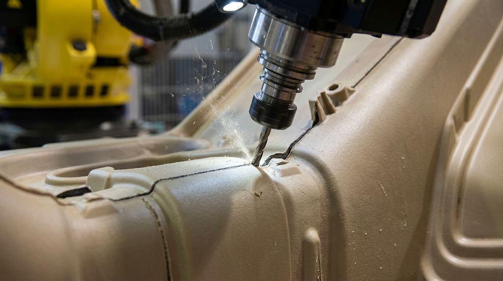
A trim path is a contour. The robot drives the cutter along the parting line at a set feed and a set depth. Consistency in both produces a uniform edge. In a typical molding application, the cut takes only a little material from the parting line. Specifically, that is often between 0.01 and 0.8 inch depending on the part. Moreover, the robot holds that depth around the whole contour. It does so even through the curves where a hand operator would slow down or dig in.
Tooling follows the material and the edge requirement. A router bit suits clean profile cuts in plastics and composites. A rotary burr or abrasive wheel, however, handles harder material or radiuses a sharp edge. On high-fiberglass parts, coated or diamond tooling earns its cost, because it survives the abrasive wear that destroys plain cutters fast.
Force Control for Variable Flash
Flash is never identical part to part. Thickness shifts with mold wear, shot pressure, and material batch. Therefore a path set to a fixed depth either misses thick flash or cuts into the part where flash is thin. A compliant or servo-controlled holder solves this. Instead of holding a fixed position, it holds constant contact pressure. As a result, the cutter rides the real edge of each part and leaves the part surface intact.
This is the line between a cell that works at volume and one that makes scrap. A rigid path with no force compensation can run well on qualification parts. However, it drifts into rejects as the mold wears. Specify force control wherever upstream flash thickness is not tightly controlled.
Programming and Simulation Offline
The trim path is built in CAM software and simulated before the robot moves. Simulation catches reach limits, collisions between spindle and fixture, and orientation changes the arm cannot make smoothly. A small kinematic error shows up as a visible edge defect. Because of that, the cell needs calibration. In practice, calibration makes the simulated path and the real path match. Shops that skip it find the gap as scrap on the first run.
4. Integration & Deployment Reality
Path accuracy and calibration decide whether the edge meets spec. The robot must follow the contour closely enough that cut depth stays inside the edge tolerance. Therefore, calibrate against the actual fixtured part, not a nominal model, and validate on real parts first.
Fixturing is process engineering, not an accessory. The fixture locates the part and holds it against cutting forces, and it defines the datum the trim path references. If the part shifts or flexes, the edge drifts no matter how good the path is. In fact, many dimensional errors start in the fixture rather than the spindle. So design the fixture to support the part along the cutter’s load path, with rest pads under any thin area.
Part presentation must stay consistent. The robot trims to a path that assumes the part sits in a known position. A part loaded off-datum produces an off-spec edge on the first cut. Where parts arrive in varying orientation, a vision system can correct the pick, but that adds cost and cycle time. Consistent mechanical location is better when the part allows it.
Dust and chip management belongs in the cell from the start. Trim debris from plastics clogs fixtures and fouls sensors. Composite dust, meanwhile, is a health hazard that demands engineering controls. Specify extraction at the cutter, sized for the material and trim volume.
5. Common Failure Modes & Constraints
| Failure | Root Cause | Signal / Symptom |
|---|---|---|
| Edge breakout or gouging | Cutter grabs brittle material; feed rate too high for tool and material | Chipped or torn edge at corners; visible gouges |
| Tool deflection | Cutter too long or slender; depth of cut too aggressive | Edge drifts from programmed dimension; cut tapers under load |
| Dimensional drift over a run | Fixture wear, part shifting, or mold wear changing flash thickness | Edge slowly moves out of spec while the program is unchanged |
| Missed flash | Fixed-depth path on variable flash, no force control | Flash stays on thick-flash parts; cutter rides over it |
| Premature tool wear | Plain tooling on abrasive material such as high-fiberglass parts | Edge quality fades within a short run; frequent tool changes |
Tool deflection deserves attention, because it looks like a programming error. When the cutter is too slender or the cut too aggressive, force bends the tool. The edge then lands off dimension even though the path is correct. First shorten and stiffen the tool, reduce depth per pass, and direct force where the spindle is strongest. Only then suspect the program.
Fixturing failures show up as scrap that climbs over time. In fact, poorly controlled setups can push scrap into the 3 to 8% range, which compounds fast at volume. A part that seats inconsistently produces errors on exactly the edges the trim operation exists to protect.
6. When It’s a Good Fit vs. a Bad Fit
Good fit when:
Robotic trimming pays off most clearly in a specific case. First, the molded or cast part has consistent parting-line geometry. Second, it runs at real volume. Third, it relies today on variable hand trimming. Parts headed for a painted or cosmetic finish benefit directly, because a consistent edge deflects paint evenly. It also fits where the manual job carries an ergonomic cost. Specifically, repetitive trimming with vibrating tools drives fatigue and carpal-tunnel injuries.
High risk when:
The risk rises when upstream flash varies widely and the plan skips force control, because a fixed-depth path cannot follow inconsistent flash. It also rises when the part is hard to fixture, since an unstable datum undermines every cut. Therefore, validate the fixture and the force-control approach on real parts, including parts from a worn mold, before committing capital.
Usually the wrong tool when:
Robotic trimming is the wrong investment for very low volumes of a constantly changing part. There, programming and fixturing each short run costs more than careful hand trimming. It is also a poor match for a single flat cut that a simple fixed router would handle faster. So run the volume and changeover numbers honestly first.
7. Key Questions Before Committing
- What edge tolerance does the next operation require, and has the cell been validated against it on real parts rather than a clean sample?
- How much does flash vary across a run and as the mold wears, and does the plan include force control rather than a fixed-depth path?
- Can the part be located and clamped consistently, and does the fixture support any thin areas along the cutter’s load path?
- Does the material need coated or diamond tooling, and is tooling cost and change frequency in the operating-cost model?
- What is the part volume and changeover rate, and does it justify a robotic cell over the alternative the shop runs today?
8. How RBTX Learn Recommends Using This Information
RBTX Learn recommends starting a trimming project with the edge specification, not the robot. First define what the trimmed edge must achieve, including the tolerance the next operation depends on. Then work backward to the path accuracy, tooling, and fixturing that deliver it. A cell specified against a real edge requirement holds spec. A cell specified against a vague goal produces edges nobody validated until parts fail downstream.
Treat fixturing and force control as the two make-or-break decisions. The fixture defines the datum every cut references. Force control, meanwhile, lets the cutter follow real, variable flash instead of an ideal path. Both are easy to underfund during specification and costly to fix after installation. Therefore, require validation on parts from a worn mold, not just fresh ones. After all, the cell has to hold spec across the whole life of the tool.