
Robotic Light Material Removal: Shallow Cuts That Stay Inside the Robot’s Comfort Zone
1. What This Resource Covers & Why It Matters
A shop wants to surface a foam styling model. Maybe it needs to skim a parting line, or true up a composite layup. The work does not need a machining center. After all, the cuts are shallow and the forces are low. However, the shop hesitates, worried the robot is not stiff enough for any milling at all. That worry is misplaced for this class of work.
Light material removal covers shallow, low-force stock removal. Surfacing foam, knocking down parting lines, and skimming excess from a layup all fit here. In robotic end milling, the cutting force runs 50 to 70% lower than a comparable fluting machine. As a result, the robot’s compliance rarely limits the work. The same flex that ruins a titanium contour simply does not show up when the cut is light.
This article shows what light material removal looks like in practice. Moreover, it covers the process parameters that keep cutting forces inside the robot’s capability. For the category basics, see the pillar on robotic milling. For heavy roughing on hard metals, see that material article instead, because the constraints there are entirely different.
2. Typical Equipment in This System
| Equipment | Role or Typical Capability |
|---|---|
| 6-axis industrial robot | Carries the spindle across the surface; provides reach to cover large foam or composite parts a fixed machine cannot |
| Milling or surfacing spindle | Drives the cutter; light removal uses moderate spindle power, often well under heavy-roughing torque needs |
| Surfacing and profile cutters | Router bits and large-diameter surfacing tools that clear shallow material in wide, even passes |
| Compliant tool holder | Holds steady contact pressure across an uneven or flexible surface, keeping cut depth consistent |
| Workholding or vacuum fixture | Secures light, flexible parts such as foam; vacuum tables hold low-density stock without crushing it |
| Dust extraction | Captures the high volume of light, airborne debris that foam and composite surfacing produce |
| Robot controller and CAM software | Generates the surfacing path offline; RoboDK, Mastercam, and Robotmaster handle the toolpath and simulation |
3. How It Works: Real-World Breakdown
Why Light Cuts Suit a Robot
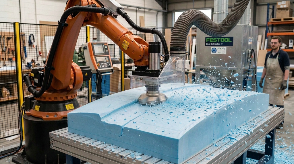
A robot arm flexes under load. On a heavy cut, that flex becomes dimensional error. On a light cut, however, the load is small, so the flex stays small too. This is the core reason light material removal is the friendliest entry point into robotic milling. The cutting force in robotic end milling runs 50 to 70% lower than a fluting machine. As a result, a low force keeps the arm inside its compliance tolerance.
Depth of cut and feed rate are the two levers that keep forces low. A shallow depth removes less material per pass, so the cutter meets less resistance. A controlled feed rate prevents the spikes that brief overloads create. In documented foam work, a force-regulated robot held cut depth at feed speeds up to 7.5 mm/s. Therefore, the goal is steady, shallow, predictable cutting rather than aggressive removal.
Keeping Contact on Uneven Surfaces
Light removal often runs across surfaces that are not perfectly flat. A foam blank may sag, and a layup may vary in thickness. As a result, a rigid path set to one depth then cuts too deep in the high spots and misses the low spots. Here a compliant tool holder solves the problem. Instead of holding a fixed position, it holds a steady contact pressure, so the cutter follows the real surface.
This matters most on flexible and low-density stock. Foam in particular deflects under even gentle pressure. As a result, the fixture and the tool holder together decide whether the finished surface is even. Specify compliance wherever the surface or the workpiece is not rigid.
Tool to Part, or Part to Tool
Light removal does not always mean the robot holds the cutter. In many cells the robot holds the workpiece instead and brings it to a fixed spindle. This configuration suits small parts well, because one robot can then run several operations against several fixed tools. Consequently, the choice between the two layouts depends on part size and weight. It also depends on how many operations the cell must perform.
4. Integration & Deployment Reality
Dust is the dominant nuisance, and sometimes the dominant hazard. Foam and composite surfacing produce a large volume of fine, airborne debris. Foam dust clogs fixtures and coats the cell. Composite dust, meanwhile, is a respiratory hazard that demands real engineering controls. Therefore, size extraction for the material and the removal volume from the start, not as a retrofit.
Fixturing flexible stock takes more thought than holding metal. A clamp that secures a steel block will crush a foam blank. Vacuum tables hold low-density stock across a wide area without point pressure, so they suit foam and thin composite well. Confirm the fixture holds the part without distorting it. After all, a part that bows under clamping mills to the wrong shape.
Surface finish expectations need setting honestly. Light removal produces a good surface for many uses. For example, a styling model or a layup ready for the next step. However, it is not a finishing pass. Where the part needs a fine final surface, plan a separate finishing operation. Otherwise, one shallow milling pass will not deliver it.
Programming is offline and simulated first. The surfacing path is built in CAM software and checked in simulation for reach and collisions. Because large surfaces involve long paths, simulation also helps optimize the pass pattern for cycle time. Calibrate the cell so the programmed surface and the real surface match.
5. Common Failure Modes & Constraints
| Failure | Root Cause | Signal / Symptom |
|---|---|---|
| Uneven surface depth | Rigid path on a sagging or variable-thickness part; no compliance | High spots cut too deep, low spots missed; visible steps in the surface |
| Foam tearing | Dull or wrong-geometry cutter; feed rate too high for the foam grade | Ragged, fuzzy edges rather than clean ones; torn cell structure |
| Workpiece distortion | Clamping pressure too high for low-density stock | Part bows under the clamp and mills to the wrong shape once released |
| Dust accumulation | Extraction undersized for the removal volume | Debris coats the cell, fouls sensors, and buries the fixture |
| Chatter on long reach | Robot extended near its limit, reducing effective stiffness | Vibration marks on the surface; audible chatter on extended passes |
Chatter is worth a closer look, because it surprises shops that assume light cuts are always safe. Even a low force can excite vibration when the arm reaches near the edge of its envelope. There, its effective stiffness drops. Keep the work inside the well-supported part of the robot’s reach, and reduce feed if vibration marks appear. Only then increase removal rate again.
Foam tearing is the other frequent complaint. A clean foam cut needs a sharp cutter and a feed rate matched to the foam grade. Too fast, and the cutter tears rather than slices, leaving a fuzzy surface. The specific tooling geometry and chip load for each foam grade belong to the foam material article. So reference it for those parameters.
6. When It’s a Good Fit vs. a Bad Fit
Good fit when:
Light material removal pays off most clearly on large, low-force work that a CNC machine cannot reach or hold. Foam styling models, master patterns, and architectural shapes are classic cases, because they are big, soft, and forgiving. Composite layup skimming and plastic parting-line removal also fit well, since both involve shallow cuts at low force. In each case, the robot’s reach is the advantage and its compliance is a non-issue.
High risk when:
The risk rises when the part flexes and the plan lacks compliance or vacuum fixturing. After all, the surface then comes out uneven. It also rises when dust control is underscoped, especially on composites. There, the debris is a health hazard rather than a housekeeping problem. Therefore, validate both the fixture and the extraction on real material before production.
Usually the wrong tool when:
Light removal is the wrong frame for work that actually needs heavy roughing or tight finishing. A deep cut in hard metal is not light removal, and it belongs in the hard-metal article instead. Likewise, a part needing a fine final finish needs a dedicated finishing step. So match the process to the real depth and finish the part requires. Do not assume one shallow pass covers everything.
7. Key Questions Before Committing
- Is the cut genuinely shallow and low-force, or does the part need heavy roughing that pushes the robot past its comfort zone?
- Does the surface or workpiece flex, and does the plan include a compliant holder or vacuum fixture to follow it?
- How much dust will the removal produce, and is extraction sized for it? Include respiratory controls if the material is composite.
- What surface finish does the part need, and does it require a separate finishing pass beyond this light removal step?
- Does the work stay inside the well-supported part of the robot’s reach? Or does it extend the arm far enough to risk chatter?
8. How RBTX Learn Recommends Using This Information
RBTX Learn recommends treating light material removal as the easiest place to prove a robotic milling cell. The forces are low, the compliance worry is largely unfounded, and the parts are often too big for CNC anyway. Start here if foam or composite surfacing is part of your work. After all, a win on light removal builds the case and the in-house skill for harder operations later.
Match the parameters to the material and keep them conservative. A shallow depth, a steady feed, and a compliant holder cover most light-removal work. Together, they keep cutting forces well inside what the robot handles. Validate on real material, including any flexible or low-density stock. After all, foam and thin layups behave differently from the rigid test blocks vendors often demo.
For material-specific tooling and parameters, follow the material articles in this series: foam, composites, and plastics. For deburring and finishing, which need force control in a different way, see that operations article. Finally, light removal is often one of several operations a single cell could run. The pillar overview maps how the operations fit together.