
Robotic Deburring and Finishing: How to Hold Consistent Edge Quality at Volume
1. What This Resource Covers & Why It Matters
A burr looks like a small problem. However, it is the problem that ruins assemblies and cuts workers’ hands. A burr that misses inspection causes misalignment, premature wear, and a part that fails on the line. Manual deburring fixes it, but with variable results. After all, no operator can hold steady pressure across a long shift on a complex edge.
Robotic deburring replaces that variability with a controlled process. So far, this sounds like trimming. Yet deburring is harder. The reason is simple: burr size is never the same twice. As a result, a fixed path cannot sense what it is actually removing. It misses thick burrs and gouges the part where burrs are thin. Therefore, the cell needs force control, not just an accurate path.
This article covers how to set up robotic deburring and finishing so the cell follows real burrs. It also explains why force control is the central design choice. For the broader category, see the pillar on robotic milling. For trimming flash on molded parts, see the trimming article. The two operations share equipment but solve different problems.
2. Typical Equipment in This System
| Equipment | Role or Typical Capability |
|---|---|
| 6-axis industrial robot | Carries the deburring tool along the edge; stiffness matters more than pure speed here |
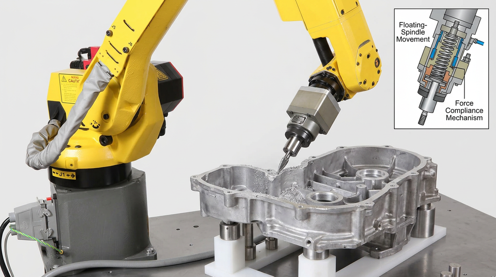
| Compliant deburring spindle | Floating spindle that holds constant force on the part while following surface variation |
| Force/torque sensor (active control) | Measures cutting force and adjusts robot trajectory to maintain target pressure |
| Cutting burrs and abrasive media | Rotary burrs for hard edges; abrasive wheels, buffing pads, and wire brushes for finishing |
| Tool changer | Lets one cell run multiple abrasives; common for parts needing both deburring and final finishing |
| Vision or referencing system | Locates a variable part before deburring; corrects the path to the actual edge |
| Part fixture or rotary table | Holds the part rigidly; rotary tables present large parts to the robot in stages |
| Dust extraction and filtration | Captures metal and abrasive debris; ATEX-rated controls where the dust is combustible |
3. How It Works: Real-World Breakdown
Passive vs. Active Compliance
Deburring tools split into two families. Passive compliance uses a mechanical mechanism. Specifically, a floating spindle, a spring, or a pneumatic cylinder lets the cutter move when it meets resistance. As a result, the tool rides the part surface even when the path is slightly off. Active compliance uses a force/torque sensor and a control loop. Here the robot reads cutting force in real time and adjusts trajectory to hold a target pressure.
Passive tools cost less and program faster. So they suit parts where burrs and location stay consistent. Active force control costs more and demands tighter integration. However, it handles variable burr size and variable part location at the same time. The choice depends on what varies in the upstream process. In practice, many cells use both: passive compliance for the bulk of work, active control where the geometry or burr varies most.
The Variability Matrix
Choose the control strategy by mapping two variables. First, does the part location vary part to part? Second, does the burr size vary part to part? When location is consistent and burr size is consistent, a programmed path works alone. If location is consistent but burr size varies, pressure control suits the job. Finally, where location varies and burr size varies, the cell needs both vision to find the part and force control to follow the burr.
This matrix is the most common source of disappointment in deburring cells. A shop specifies pressure control alone for parts that also drift in location. Then the path lands in the wrong place, and pressure control alone cannot recover. Therefore, map both variables honestly before choosing a configuration.
Surface Roughness as the Spec
Deburring without a measurable target produces edges nobody can validate. Instead, write the spec as a surface roughness value, typically Ra in micrometers. Specifically, automotive and aerospace parts often carry a defined Ra requirement from the drawing. Then the cell is tuned to hit that number. After tuning, surface roughness measurement on production parts confirms the cell holds spec over a run.
Tool choice drives the achievable Ra. Burr geometry, abrasive grit, and cutting force all show up in the final surface. Where a part needs both deburring and a fine finish, a tool changer lets one cell run a deburring pass and then a finishing pass with different media.
4. Integration & Deployment Reality
Fixturing must be repeatable. Without consistent part repeatability, no path produces reliable results. So design the fixture to seat the part the same way every time. Where parts vary or arrive in different orientations, a vision system corrects the path. Vision adds cost and cycle time, however, so consistent mechanical location is preferable when the part allows it.
Tool wear shifts the result. Burrs and abrasive media wear during a run. As they wear, the same path removes less material, so edges drift toward under-deburring. Therefore, plan tool change intervals into the cell, and monitor surface finish on sample parts through a run. Pure burr count is not enough; the inspection has to confirm the Ra target still holds.
Dust and debris management is mandatory. Deburring metal produces fine particulate that becomes airborne. Composite or aluminum dust raises additional safety concerns, including combustibility. ATEX-rated extraction is required for some materials. Likewise, specify filtration sized for the removal volume from the start.
Programming is offline and validated on real parts. CAM software builds the path and simulates reach and collisions. Calibration aligns the simulated path to the real cell. However, calibration alone is not enough for deburring. The cell needs validation on production parts with real, variable burrs. After all, a qualification part with consistent burrs hides the variability problem.
5. Common Failure Modes & Constraints
| Failure | Root Cause | Signal / Symptom |
|---|---|---|
| Gouged surface | Path off-location, no compliance to back it off; fixed-depth contact with variable burr | Visible dig marks where the cutter cut into the part beyond the edge |
| Burrs left on the part | Compliance set too soft; tool wear unaccounted for; pressure too low | Burrs still present after the pass; finish fails inspection |
| Inconsistent edge across a run | Tool wear shifting cutter geometry; abrasive loaded with debris | Surface roughness drifts within a single run; first and last parts measure differently |
| Path drift on variable parts | No vision or referencing where part location varies | Cutter lands off-edge on some parts even though the program is unchanged |
| Tool shank breakage | Cutter rigid where it should flex; sudden force spikes on heavy burrs | Snapped cutter; abrupt scrap event mid-run |
Tool wear deserves a specific note, because it sneaks up on a cell that runs well at acceptance. Cutters and abrasives lose their cutting edge gradually, and the same programmed pressure then removes less material. Therefore, inspect Ra on sample parts through a production run, not only at the start. So tool change intervals should be set conservatively first, then extended as data supports it.
Path drift on variable parts is the other recurring failure. A cell tuned for one nominal part location holds spec until upstream variation grows. Then edges land off-target across the run. Where part location varies even slightly, vision earns its cost by correcting the path before each part.
6. When It’s a Good Fit vs. a Bad Fit
Good fit when:
Robotic deburring pays off most clearly on parts with consistent geometry, real production volume, and a measurable Ra or edge-break spec. Cast and machined parts in automotive, aerospace, and heavy equipment all fit, since these industries already write the spec on the drawing. Parts with sharp edges that cause laceration injuries during manual deburring make the case even stronger. After all, a robot removes the worker from the injury exposure entirely.
High risk when:
The risk rises when burr size or part location varies widely and the plan skips force control or vision. So a fixed-path cell will then drift into scrap as variability shows up. It also rises when the surface finish spec is not defined upfront. Without a measurable target, no one knows whether the cell holds spec. Therefore, write the Ra requirement before specifying equipment.
Usually the wrong tool when:
Robotic deburring is the wrong investment for very low volumes of constantly changing parts. There, programming and fixturing each setup costs more than skilled hand work. It is also wrong where the edge requirement is loose enough that a quick hand pass meets it. So run the volume, spec, and ergonomic cost honestly first before automating.
7. Key Questions Before Committing
- What surface roughness or edge-break spec does the part actually require, and is it written down before equipment selection begins?
- Does burr size vary across a production run, and does the plan include force control to follow that variation?
- Does part location vary on the fixture, and does the cell include vision or referencing to correct the path?
- How does tool wear get monitored, and are change intervals tied to measured surface finish rather than guesswork?
- Does the dust or debris demand ATEX-rated extraction, and is filtration sized for the real removal volume?
8. How RBTX Learn Recommends Using This Information
RBTX Learn recommends starting a deburring project with the spec, not the robot. First write down the Ra or edge-break requirement the next operation depends on. Then map what varies upstream: part location, burr size, or both. Together, those two answers determine whether the cell needs passive compliance, active force control, vision, or some combination. Skipping that mapping is the single most common reason a deburring cell underperforms after installation.
Treat force control as the design decision, not a feature. Passive compliance handles consistent burrs cheaply. Active force control handles variable burrs at higher cost. The choice depends on the upstream process, not on the robot. Therefore, validate on production parts with real burr variation before sign-off, including parts from a worn upstream tool. After all, a deburring cell that holds spec only on clean qualification parts misses the actual job.
For material-specific abrasive and tool choice, follow the material articles in this series: foam, composites, plastics, and hard-to-machine metals. To weigh deburring against the manual operation it replaces, see the manual-machining comparison. Finally, deburring is often one of several operations a cell could run. The pillar overview maps how the operations fit together.