
Fairino FR5 on a 7th Axis vs. Two UR7e Cobots: Can One Robot Tend Two Machines?
The default layout for cobot machine tending puts one robot at each machine. Universal Robots calls a one-to-one ratio of cobot to machine the basic configuration, though one cobot can cover two or three machines when cycle times and layout allow.
The second robot is often the largest line on the bill, and in a long-cycle cell it spends most of the shift waiting for a door to open. A 7th axis lets one arm drive between machines instead — but if it is busy at one machine when the other finishes, that spindle sits idle until the arm arrives.
Below, a Fairino FR5 on an igus® 7th axis goes up against two Universal Robots UR7e cobots, each tending one machine. The schedule math comes first, followed by integration, floor space, downtime, hardware cost, and the cases where a second robot earns its price.
How Each Setup Works
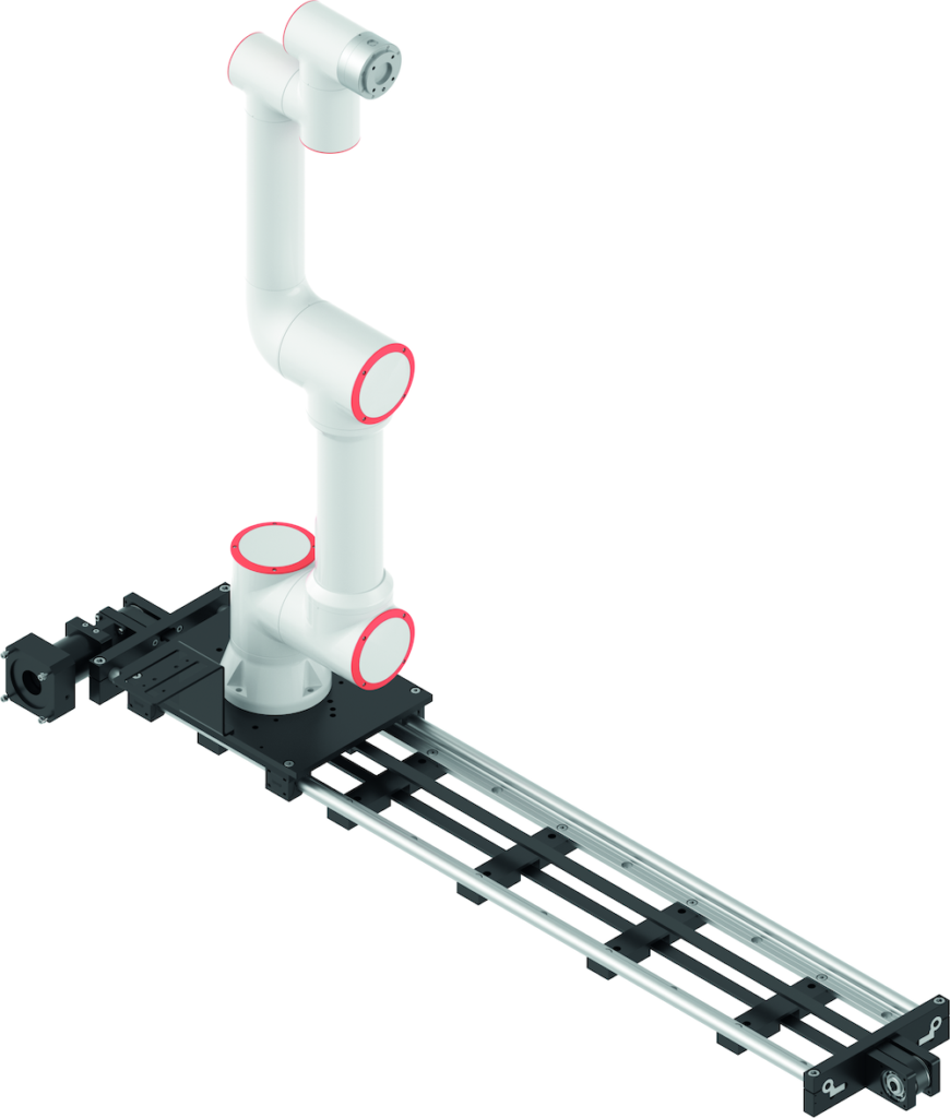
Fairino FR5 on a 7th Axis
The FR5 is a 6-axis cobot with a 5 kg payload, 922 mm reach, and ±0.02 mm repeatability. Mounted on the 7th axis, it gains up to 3,000 mm of straight-line travel as standard, with longer strokes on request. The carriage is rated for 55 kg, so the 22 kg arm leaves room for tooling and parts.
The 7th axis travels at up to 0.3 m/s and repeats to ±0.3 mm. It takes commands through digital I/O, so the FR5’s own program can call each machine position without a separate master controller.
Two UR7e Cobots
The UR7e carries 7.5 kg over an 850 mm reach with ±0.03 mm repeatability, on a 151 mm base. Each robot stands at one machine with its own controller and teach pendant, so the cell never has to choose which door to serve first.
Side-by-side comparison: a loose winner for each parameter
| Parameter | FR5 on a 7th axis | Two UR7e cobots | Loose winner |
|---|---|---|---|
| Payload | 5 kg | 7.5 kg each | Two UR7e |
| Reach | 922 mm, plus up to 3,000 mm of travel | 850 mm each | FR5 on a 7th axis |
| Repeatability at the machine | ±0.02 mm arm on a ±0.3 mm carriage | ±0.03 mm | Two UR7e |
| Response when both machines call | One machine waits | Both served at once | Two UR7e |
| Robot utilization | One arm shared across two machines | Each arm idle through most of its machine’s cycle | FR5 on a 7th axis |
| Floor space | One strip along the machine fronts | Two pedestals and two controllers | FR5 on a 7th axis (layout-dependent) |
| Programs and controllers | One | Two | FR5 on a 7th axis |
| Effect of a robot fault | Both machines lose automation | One machine loses automation | Two UR7e |
| Hardware cost | Lower | Higher | FR5 on a 7th axis |
The traveling cell wins on cost, space, and robot use. The stationary pair wins on response, payload, and fault isolation, and the schedule decides which list matters more.
The repeatability row matters most at the fixture. The ±0.3 mm carriage, not the ±0.02 mm arm, sets placement at each machine. Chamfered vise jaws or a chuck with lead-in absorb that easily, but a tight-fitting fixture needs a locating feature or a reference check at each station.
Can One Robot Keep Up with Two Machines?
Processing Time and Handling Time
Processing time is when the machine runs on its own with the door closed. Handling time is everything the robot does at the door: open, unload, load, close, and signal cycle start. While machine A processes, the traveling robot must drive to machine B, serve it, and drive back, so processing time must exceed one handling time plus two trips or machine A waits.
Travel Time on the 7th Axis
At 0.3 m/s, the 7th axis covers 2.5 m in just over 8 seconds at full speed, before acceleration and deceleration are added. Travel is the only term in the rule fixed by hardware, which makes machine placement the cheapest cycle-time lever — every meter between load points adds more than 3 seconds to each trip.
Hypothetical Example with Illustrative Values
- Load points 2.5 m apart, with travel assumed at 10 seconds per trip including acceleration.
- Handling time of 40 seconds per visit, and processing time of 180 seconds on each machine.
- Robot loop while machine A runs: 10 + 40 + 10 = 60 seconds, which leaves 120 seconds of slack.
- The FR5 is busy 100 of every 220 seconds, or about 45% of the time. Each UR7e in a two-robot cell would be busy about 18%.
- At 60 seconds of processing time the slack reaches zero. Below that, each machine waits on every cycle.
Leave margin above break-even. Processing times drift with tool wear, probing routines, and part variation, so size the slack against measured cycles rather than the CAM estimate.
Simultaneous Demand
Identical cycles settle into an alternating rhythm on their own. A tool change, an alarm reset, or different part programs can pull the machines back into step so both doors open at once. One machine then waits a full handling time plus a trip, and on mixed work that collision can recur cycle after cycle.
A dual gripper swaps the finished part for a blank in one stop, which shortens every visit. A priority rule in the robot program decides which door to serve first when both call, so the loss lands where it costs least.
Integration and Floor Space
Controllers, I/O, and Programming
In the traveling cell, one controller runs door, workholding, and cycle signals for two machines, plus the 7th axis calls. The I/O map roughly doubles, but one program covers the whole cell, and a new part on either machine is taught from the same WebApp or teach pendant.
With two UR7e cells commissioned one at a time, the second program is often a near-copy of the first, and a fault stays in its own cell. The trade is two controllers and two programs to keep in step whenever the process changes.
The moving arm’s power, signal, and air lines also have to follow the carriage. An e-chain® cable carrier beside the 7th axis guides them along the stroke, so cables don’t drag or snag on the machine fronts.
Floor Space and Safety
The 7th axis occupies one narrow strip along the machine fronts, while each stationary cobot needs its own pedestal, controller, and clear space. In a published two-lathe simulation, one robot on a 7th axis fit in less floor area than two robots, though the study used industrial arms rather than cobots.
The trade is a moving hazard zone. The risk assessment has to cover the FR5’s reach along the full stroke, including any aisle beside the machines.
Downtime and Redundancy
The traveling cell has a single point of failure: if the FR5 or the 7th axis stops, both machines go back to manual loading. With two UR7e cobots, a robot fault idles one machine instead of two, and the healthy cell keeps running through the repair.
Planned maintenance follows the same pattern. The traveling cell has one arm to service plus a 7th axis built on self-lubricating drylin® linear technology, while two dedicated cells mean two arms on separate schedules.
The deciding question is who loads the machines during an outage. On a staffed shift, a robot fault costs operator hours. In a lights-out shift, it costs every part both machines would have made until someone arrives.
Total Installed Cost
On hardware alone, one FR5 plus a 7th axis lists well below two UR7e cobots ($11,600.79 vs. $38,363). Part of that gap comes from brand tier rather than layout, since the FR5 sits in a lower price class than the UR7e.
The 7th axis also supports Universal Robots arms, so the cleaner layout-only comparison is one UR7e on a 7th axis against two UR7e cobots. In that pairing, the saving equals one arm minus the 7th axis, and it narrows as the stroke grows.
Grippers, guarding, machine interfaces, and integration labor apply to both layouts, although the traveling cell buys one set of tooling where the stationary pair buys two.
When Two Dedicated Robots Justify the Extra Investment
- Short machine cycles. When processing time falls below one handling time plus two trips, the traveling robot makes each machine wait on every cycle.
- Machines beyond one straight stroke. The 7th axis travels in a straight line up to 3,000 mm (9.8 ft) as standard. Machines across an aisle, set at an angle, or farther apart need a custom stroke or a second robot.
- Heavier tooling. A dual gripper and a steel part can exceed the FR5’s 5 kg payload, where the UR7e’s 7.5 kg adds margin.
- Strict uptime commitments. Where a stopped robot means a missed shipment, two cells halve the exposure.
- Unrelated work on each machine. Different part families with unsynchronized cycles produce frequent simultaneous demand.
- Tight fixture seating. If the fixture can’t accept ±0.3 mm of carriage variation, a stationary arm at ±0.03 mm is simpler than adding locating features.
Outside those cases, one traveling arm usually does the work of two. Long, stable cycles on neighboring machines are where the FR5 on a 7th axis fits best.
Questions to Answer Before Commiting
- What are the measured processing times on each machine, and how much do they vary?
- How long does the robot spend at each door with the gripper you plan to use?
- How far apart are the load points, and do they sit on one straight line?
- How often will both machines finish within a few seconds of each other?
- What does the full tool weigh, including a second gripper?
- How would the plant load both machines if the robot were down for a shift?
Run the two-trip rule on your own cycle times first. An RBTX expert can model both layouts against the same pair of machines and help build the complete system around the one that fits.