
RBTXpert Debrief: What are Automation Guarding Safety Standards, and What Does Hardware Look Like?
Partner Resource: item America, How to build safety guards that comply with US Machine Safety Regulations and Standards.
Content Type: Compliance and Design Guide.
Best For: Automation engineers and safety engineers designing robotic cells and automated production lines.
Who Should Read This
You are specifying guarding for a new robot cell. OSHA says the hazard must be guarded, and your integrator can build the guard. What you still need is which standards the design will be judged against, which numbers drive the layout, and what to ask for before you sign off.
That means automation and safety engineers, the plant engineers who approve layouts, integrators, and the maintenance leads who write the lockout procedures the design has to support. Operators and technicians live with every door and lockout step it creates, and purchasing should know that guarding, sensors, and validation time belong in the cell budget.
What This Covers
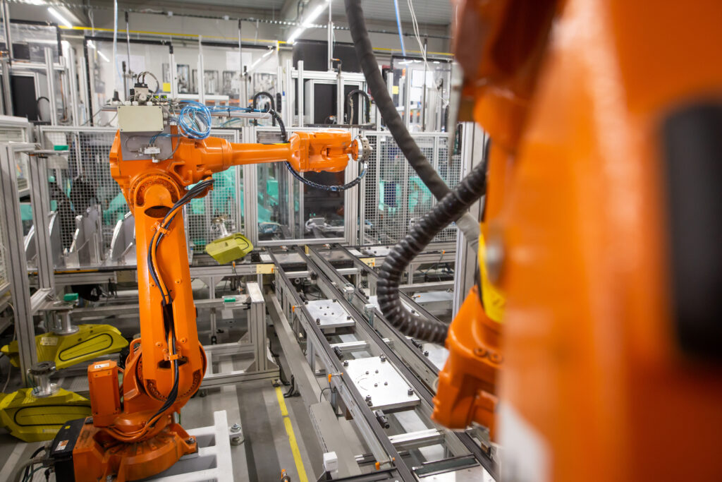
item’s guide lays out the US regulatory structure for machine guarding. OSHA 29 CFR 1910 Subpart O is the enforceable rule, and the ANSI B11 series supplies the consensus standards OSHA leans on. The guide explains when a risk assessment under ANSI B11.0 calls for a guard, then summarizes the ANSI B11.19 performance criteria: strength, impact resistance, tamper resistance, visibility, and secure mounting.
It also distinguishes simple interlocks from interlocks with guard locking. It lists the factors that set safety distance: guard height, opening size, hazard location, and reach. Finally, it shows how item’s guard components and design tools map to those requirements.
The RBTXpert Take
Standards First, Hardware Second
item’s guide is written for guarding any machine, so it builds on the ANSI B11 series. That is the right frame for a guard supplier. If the thing inside your guard is an industrial robot, a second standard applies.
OSHA has no robot-specific rule. A robot cell is judged against the general machine guarding requirements in Subpart O, lockout/tagout under 1910.147, and the General Duty Clause. Consensus standards fill in what adequate protection looks like, and for robots that standard is ANSI/A3 R15.06.
The current edition, R15.06-2025, is the US adoption of ISO 10218-1 and ISO 10218-2 (2025 editions). It replaces the 2012 edition that older cell documentation will cite. It has three parts:
- Part 1 covers the robot itself, for manufacturers
- Part 2 covers robot applications and cells, for integrators
- Part 3, Use of Industrial Robot Cells, was written in the US for the companies that run the cells.
Four changes matter most for cell design:
- Collaborative-application guidance from ISO/TS 15066 is now consolidated into the standard.
- New content covers end-effectors and manual load/unload stations.
- “Safety-rated monitored stop” is now called “monitored standstill.”
- Cybersecurity is treated as part of safety planning.
What to do with this: Ask your integrator which edition the cell’s risk assessment cites. If it cites the 2012 edition, or treats ISO/TS 15066 as a standalone document, ask whether it has been reviewed against 2025. An older cell is not automatically out of compliance. OSHA has said it is the employer’s job to judge whether a revised standard’s changes are needed to protect employees.
The ANSI standards are voluntary and OSHA’s regulations are enforceable, but in practice the voluntary standards are what your guard gets compared against. You can control a hazard another way; a departure from B11.19 or R15.06 is just something your risk assessment has to justify.
Keep one fact in view as you design. OSHA notes that many robot accidents happen during non-routine work such as programming, maintenance, testing, setup, and adjustment, when someone is often inside the robot’s envelope. Guarding a robot cell is as much about designing safe access as about keeping people out.
Choosing a Safeguarding Method
The real question is not guard or no guard. It is how often people need to be inside the cell, and why.
| Method | Fits when | What it demands | Where it typically falls |
|---|---|---|---|
| Design out access (automated load/unload, pass-through conveyors) | Normal production needs no one inside the cell | A plan for non-routine access, which still happens | Setup, clearing, and maintenance still bring people in |
| Fixed perimeter guard | Entry is rare and planned | Openings and distances sized to reach limits; panels that need tools to remove | Panels left off after maintenance; people reaching over a guard that is too low |
| Interlocked guard (access door) | People enter routinely for loading, changeover, or clearing | An interlock matched to the risk; guard locking if the robot cannot stop before someone reaches it; periodic function tests | Switches defeated to save time; interlocks treated as a substitute for lockout during maintenance |
| Presence-sensing device (light curtain, laser scanner, safety mat) | Access is frequent and a door would slow the operator | A measured stop time, a calculated safety distance, and a deliberate reset before restart | Mounted too close for the robot’s actual stopping time |
| Collaborative operation (power and force limiting, speed and separation monitoring, hand guiding, monitored standstill) | People and robot genuinely share the workspace | A risk assessment of the whole application, including tool, part, and fixtures | A sharp, hot, or heavy tool or part that makes contact unsafe, whatever the arm does |
Light curtains and scanners are engineered safeguards, not behavioral controls. They don’t physically block a reach, though. Their protection depends on stopping the robot before a hand arrives, which is why the distance math below matters.
For collaborative operation, the risk assessment covers the application, not the arm. A robot running a welding torch or moving sharp sheet metal is not suited to working beside people, however collaborative the arm is. The same goes for heavy parts that could be dropped or thrown.
Methods can also be combined. One cell might pair a fixed perimeter with an interlocked maintenance door and a light curtain at the load station. A cobot cell might need no fence at all, but use a scanner that slows the robot as someone approaches.
Fixed Guards: The Numbers That Set the Layout
item’s guide explains the principle correctly: larger openings and lower guards mean the guard has to sit farther from the hazard. Here are the numbers behind that principle.
Openings. OSHA’s Table O-10, written for mechanical power presses, is the US regulatory reference for guard openings. It caps openings at 6 inches, and only at roughly 31½ inches from the hazard. Smaller openings are allowed closer in. Guard openings are commonly checked with a guard opening scale, a stepped gauge shaped like a hand and forearm.
Mesh panels. Under ISO 13857, a 40 × 40 mm mesh needs 200 mm between the fence and the hazard. That assumes the fence is tall enough that no one can reach over it; a lower fence needs more distance. Finer mesh can sit closer.
Where you measure from. For a robot cell, that 200 mm is measured to the outer edge of the robot’s restricted space, not its operating space. The restricted space is the envelope the robot is prevented from leaving. Hard stops can limit the base axis, and electromechanical devices or safety-rated software can limit the others. Software or electronic limits must meet PL d with category 3.
The operating space is only where the program happens to move the robot, which is not a safe limit. Collision detection and over-current protection don’t count as limiting devices either, unless they were specifically designed and tested as safety devices.
A fence can itself act as the limiting device only when the robot cannot deform it dangerously. In practice that means small robots behind solid panels, with the integrator verifying by calculation and test that the guard can withstand the robot.
Impact. US standards ask guards to withstand reasonable and foreseeable impacts, without naming a number. If you want a benchmark to specify, ISO 14120 includes an informative annex describing a fence test. It simulates a person walking into the fence at 115 J and objects thrown from inside the cell. The annex is not mandatory, but asking whether panels were tested this way gives you a comparable basis between suppliers.
What to do with this: Ask your integrator for a drawing of the restricted space and how it is enforced. Confirm that fence distances are measured from that boundary. If you are choosing a robot, check whether it offers safety-rated zone or joint limiting, because that is what lets you pull the fence in.
Presence-Sensing Devices: The Math the Source Leaves Out
A light curtain, scanner, or mat protects people only if the robot stops before a hand reaches the hazard. How far back it has to sit is a calculation:
Ds = (K)*(Ts + Tc + Tr + Tbm) + Dpf
- Ds is the minimum distance from the sensing field to the hazard.
- K is the hand-speed constant, 63 inches per second.
- Ts is the machine’s stopping time, measured under worst-case conditions.
- Tc and Tr are the response times of the control system and the sensing device.
- Tbm is extra time for brake monitoring, where it applies.
- Dpf is the penetration depth factor: how far a hand can travel into the sensing field before it is detected. It depends on the device’s resolution.
Every 100 ms of stopping time adds 6.3 inches. And the detection method matters as much as the timing: ANSI B11.19 puts the penetration factor for safety mats at 48 inches, because a mat detects feet, not a reaching hand. As an illustration, a 0.30 s stop time plus 0.02 s of controller response and 0.015 s of curtain response gives 63 × 0.335, about 21.1 inches, before Dpf.
Robot stopping time is not a single number. It changes with speed, payload, and arm extension. Epson’s robot manuals, for example, chart stopping time and distance at 33, 66, and 100 percent of speed, payload, and arm extension. Use the worst case your program and tooling will run.
Published data is for planning. OSHA’s guidance calls for measuring stop time on the installed machine with a stop-time measurement device, and repeating that as brakes wear. Blanked light-curtain channels add distance too.
What to do with this: Ask the robot vendor for stopping data at the speed and payload you will run, then ask the integrator for the measured stop time and the distance calculation behind every sensing device in the cell.
Interlocks, Access, and Lockout/Tagout
item’s guide draws the key distinction. A simple interlock is enough when opening the guard stops the hazard immediately; guard locking is needed when motion continues after the stop signal. The guide also notes that guard locking can be arranged so the machine keeps running when access is part of the process, such as a quality check. For a robot, the stopping data answers which one you need: if someone can open the door and reach the robot before it stops, use guard locking or move the door back.
The harder question is what happens once they are inside, because two OSHA rulebooks apply. Normal production, such as loading a fixture, falls under Subpart O. Servicing and maintenance falls under lockout/tagout, 29 CFR 1910.147, and OSHA defines servicing broadly: setting up, adjusting, inspecting, cleaning, unjamming, and tool changes all count. Servicing during production is covered if someone removes or bypasses a guard, or puts part of their body into a danger zone. The exception is minor servicing that is routine, repetitive, and integral to production, and only with alternative measures that provide effective protection. OSHA’s examples include clearing jams, minor cleaning, and small adjustments.
Two details decide whether your interlocks qualify. OSHA’s rule says push buttons, selector switches, and other control-circuit devices are not energy isolating devices, so an interlock switch never replaces lockout. And in OSHA’s interpretations, control-circuit devices alone are not effective alternative protection. That generally means the machine stopped, the person doing the work holding exclusive control of restarting it, and stored energy controlled. Where several people service a machine together, OSHA generally does not treat the work as minor.
| Task type | Robot cell examples | Rulebook | Typical protection |
|---|---|---|---|
| Production access | Loading a fixture, a designed-in quality check | Subpart O | Interlocked door with guard locking, light curtain, or monitored standstill |
| Minor servicing | Clearing a routine jam, wiping a sensor, a small adjustment | The 1910.147 exception, if all its criteria are met | Robot stopped, restart under the servicing person’s exclusive control, stored energy controlled |
| Servicing and maintenance | Gripper repair, drive or cable replacement, anything needing disassembly or a second person | 1910.147 in full | Lockout on energy isolating devices, per a written procedure |
Programming and teaching inside the cell is its own case, which R15.06 addresses with reduced-speed operation and an enabling device held by the programmer.
Two procurement points follow. OSHA requires energy isolating devices on newly installed equipment to accept a lockout device, so specify lockable electrical and pneumatic disconnects. Lockout also requires stored energy to be relieved or restrained, which here means gripper and fixture air, and axes that can move under gravity. And interlocks are hardware that fails: switches, locking solenoids, and safety relays need their own test schedule, and lockout procedures must be inspected at least annually.
What the Hardware Looks Like
Cell guarding is four layers: a frame, infill panels, access points, and the devices mounted on them.
The frame is posts and rails, usually aluminum profile or steel, anchored to the floor. Bolted profile systems let you add a door or reconfigure later; item’s guide points to its Clamp Profile 8 40×40, which clamps panels to the profile for a rigid guard.
The infill decides what the guard contains, not just whom it keeps out. Wire mesh stops people and large parts at the right distance but passes chips, fluids, sparks, and light. A clear solid panel contains chips, fluids, and small parts while keeping the view, and it is what you need where the guard must also contain the robot. Sheet metal contains everything including the view, so add windows where operators need to see in. item’s guide makes the same point about solid panels and ejected parts, splashing liquids, and emissions. Welding cells add a requirement: OSHA requires workers next to arc welding to be protected from the rays by noncombustible or flameproof screens or shields, or by goggles, and it has accepted transparent plastic screens that are flameproof and absorb the rays.
Access points are hinged or sliding doors for routine entry and removable panels for maintenance. Panels should need tools, and it should be obvious when one is off; item’s Safety Hanger is one example, creating a visible change when a panel is detached. Conveyor pass-throughs are openings too, so size them with the rules above, and don’t forget the gap at the bottom, which item fixes at 170 mm.
Expect interlock switches or locks at each door, a light curtain at any open load station, emergency stops at access points, and a reset placed where the person pressing it can see that the cell is empty.
Final Notes
item’s guide is a clear map of the US machine-guarding framework. Its summary of the B11.19 criteria is accurate, and its tamper-resistance points are right: removable panels should need tools, and a missing panel should be obvious. Because it is written for guarding any machine, the robot-specific layers are what a cell designer has to add. Budget for validation as well, since stop-time measurement and function testing only happen once the cell is built.
Questions for your integrator:
- Which edition of R15.06 does the risk assessment cite? If 2012, has it been reviewed against 2025?
- Which tasks did it cover? Setup, jam clearing, maintenance, and programming should all be on the list.
- Where is the robot’s restricted space, how is it enforced, and at what performance level?
- Are fence distances measured from that boundary, and which opening and distance pairs were used?
- What stop time was measured on the installed robot, and where is the calculation for each curtain, scanner, or mat?
- How is each access task classified, and what protection covers each?
- Where are the lockable isolation points, including pneumatics, and how is stored energy released?
- Were the guard panels impact-tested, by what method, and what is the test schedule for interlocks, curtains, and emergency stops?
Read the full item America guide on safety guard compliance here.