
Silicone Dispensing Automation: Form-in-Place Gaskets and RTV Applications
1. Dispensing Silicones: Form-in-Place Gaskets and RTV Applications
What This Covers and Why It Matters
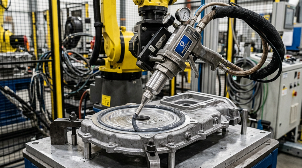
Form-in-place gasketing is one of the highest-volume automated dispensing applications in manufacturing. Instead of cutting, inventorying, and placing a preformed gasket, a robot dispenses a precise bead of liquid silicone directly onto the mating flange. The mating part assembles over it, compresses the bead, and the material cures in position to form a continuous custom seal. RTV silicone has dominated this application since Japanese manufacturers pioneered liquid gasketing on engine assemblies in the 1970s, with ThreeBond International among the first suppliers to bring it to automotive OEMs at scale.
Today, FIPG is standard on engine oil pans, transmission housings, gearbox covers, cooling system components, and increasingly on EV battery enclosures and electronic control units. The application is straightforward in concept and demanding in practice. Surface preparation, cure timing, bead geometry, and material chemistry all interact in ways that produce expensive field failures when any one variable drifts.
Typical Equipment in This System
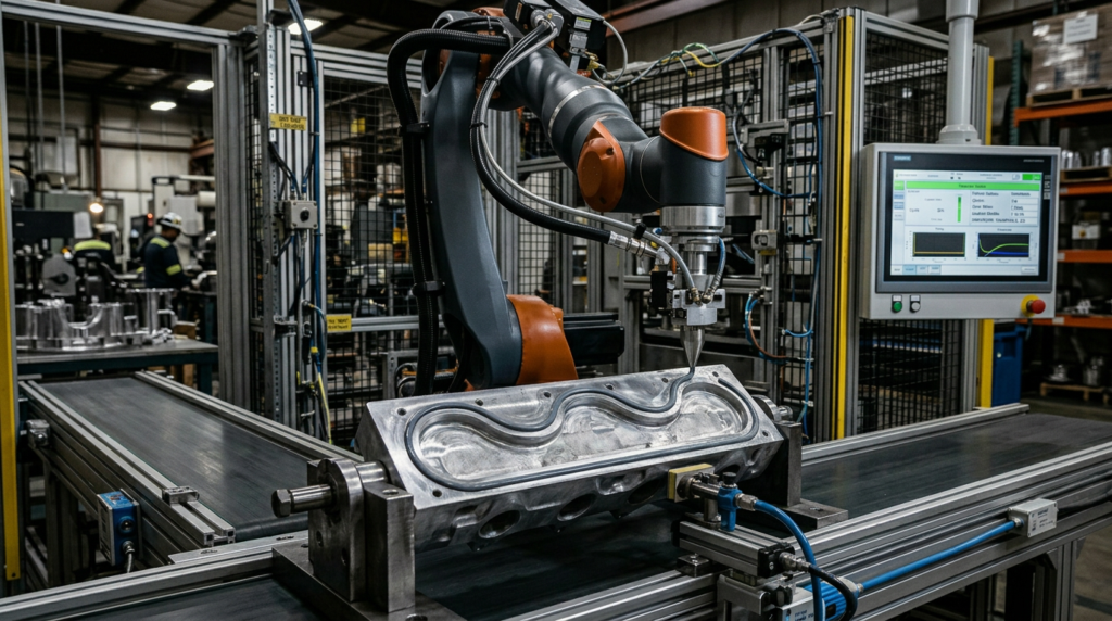
| Equipment | Role or Typical Capability |
|---|---|
| 6-axis dispensing robot | Follows complex 3D flange geometry at consistent standoff height and TCP speed; FANUC M-10iD and ABB IRB 2600 are common for automotive housing applications |
| Progressive cavity pump | Delivers consistent volume per revolution independent of viscosity change; Viscotec eco-PEN450 and Nordson EFD 797PCP are industry standards for RTV silicone dispensing |
| Heated supply hose and reservoir | Maintains silicone temperature within ±1°C from drum to nozzle tip; critical for high-viscosity grades where ambient temperature swings affect bead width |
| Tapered dispensing nozzle | Orifice diameter selected for target bead geometry and material viscosity; wear item requiring cycle-count-based replacement |
| Inline laser profilometer | Measures bead width, height, and continuity immediately after dispensing; Keyence LJ-X series and Coherix sensor rings are common integrations |
| Plasma or IPA cleaning station | Removes oil, machining residue, and surface oxidation before dispensing; adhesion reliability depends directly on this upstream step |
How It Works
RTV Chemistry and Why Cure Chemistry Selection Matters
RTV stands for Room Temperature Vulcanizing. The material crosslinks and cures through reaction with atmospheric moisture, progressing from the surface inward. The skin forms in 5 to 45 minutes depending on humidity. Full cure penetrates approximately 2 to 3 mm per 24-hour period at 25°C and 50% relative humidity. In cold, dry facilities, that timeline extends significantly. In warm, humid environments, it shortens. Consequently, the cure schedule must be confirmed against the actual production environment rather than the material data sheet’s standard conditions. This single-component, moisture-cure mechanism is what places RTV silicone firmly in the one-part adhesive category, with the simpler operational profile that comes with it.
Cure chemistry selection carries more consequence than most operations realize. Three systems dominate production FIPG: acetoxy, alkoxy, and oxime. Acetoxy cure is fast and widely available, but it releases acetic acid as a byproduct, which is one of several chemical hazards worth reviewing during cell safety design. That acid attacks aluminum, copper, and steel surfaces. On cast aluminum transmission and engine housings, acetoxy cure RTV is therefore generally excluded in favor of neutral-cure alkoxy or oxime chemistry. Neutral cure systems release alcohol or oxime byproducts instead, which do not corrode metal substrates.
Electronics FIPG applications add a further constraint. Henkel’s Loctite SI 5972FC uses a tin-free alkoxy catalyst to meet REACH compliance requirements. It also builds enough early green strength to pass a 3 PSI leak test immediately after assembly, which addresses production lines where staging space for full 24-hour cure is unavailable. ThreeBond’s 1200-series silicone RTVs cover the automotive powertrain range: TB1207B and TB1216E for oil pans and pump housings rated to -60°C through +250°C, TB1227D for housings requiring oil and coolant compatibility, and TB1222C for flame-retardant applications meeting UL94V-0. Match the chemistry and fluid compatibility to the application before any dispensing equipment is specified.
Substrate Preparation: The Step That Determines Whether the Seal Lasts
Brighton Science’s FIPG application engineering team frames this clearly: surface cleanliness for FIPG is a molecular-scale problem, not a visual inspection problem. A flange that looks clean carries oil residue, oxidation, and environmental contaminants at the molecular level that prevent RTV from forming a reliable adhesive bond. In practice, defining “clean enough” requires contact angle measurement rather than visual or particulate-level inspection.
Two timing variables govern surface preparation. First, the cleanliness level achieved immediately after the cleaning step. Second, the time elapsed between cleaning and dispensing. Once a surface generates a fresh molecular state through plasma treatment, IPA wiping, or washing, environmental contaminants begin redepositing. A surface cleaned 30 minutes before dispensing is measurably less receptive to adhesion than one cleaned immediately before. Moreover, the production cell must control this interval consistently, not just during process development.
Plasma treatment is increasingly specified for aluminum powertrain housings because machining coolant leaves oil-based residue that IPA alone does not reliably remove. For operations where IPA wiping is the cleaning method, the wiping technique itself must be controlled. Wiping with a contaminated cloth or solvent that has already picked up residue from previous parts simply redistributes contamination rather than removing it.
Flange Design and Bead Geometry
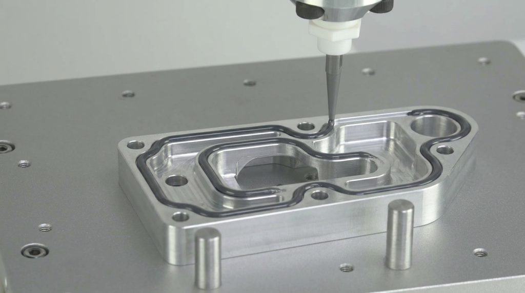
FIPG performs differently from a solid gasket in one fundamental way: the liquid bead flows into surface irregularities and cures to 100% contact. However, this performance depends on correct flange geometry. The most common FIPG design mistake, documented by Adhesives and Sealants Industry, is designing the flange for a solid gasket and then substituting liquid silicone without adjusting the flange dimensions.
Liquid gaskets require a flange wide enough to contain the bead under compression without squeeze-out reaching fastener holes or internal passages. The balance between metal contact width, bead cross-section volume, and compression distance determines whether the seal holds or fails. For most automotive housing applications, bead dimensions run 3 to 5 mm wide and 2 to 4 mm tall before compression. After 30% to 50% compression at assembly, the bead fills the gap and contacts both flanges continuously.
A bead that is too small leaves thin spots. Too large generates squeeze-out that may enter oil passages or bolt holes. Both produce field failures that trace back to the same bead control fundamentals that govern every dispensing cell. Verify bead volume against the available flange channel volume at full compression before finalizing the dispense program. This is a calculation, not a trial-and-error exercise.
Assembly Timing and Open Time Management
After dispensing, RTV must be compressed between the mating surfaces before the surface skin closes. Once skinning occurs, the material loses adhesion to the second substrate. ThreeBond’s FIPG documentation confirms that dispensing onto a part and then allowing it to sit too long, such as during a production break, causes reduced adhesion and sealant failure.
The production cell must therefore control dispense-to-assembly time as a process parameter. The line management system should enforce this interval rather than leaving it to operator judgment. If the line stops after dispensing but before assembly, the cell needs a defined decision rule: does the dispensed part proceed to assembly or return for cleaning and re-dispensing? Operating without this rule produces variable open time exposure across the production run, which generates adhesion variability that is difficult to trace back to the timing gap.
Common Failure Modes and Constraints
| Failure | Root Cause | Signal or Symptom |
|---|---|---|
| Adhesion failure at flange interface | Surface contamination; RTV skinned over before mating surface contact | Gasket peels cleanly from flange; leak at metal-silicone interface rather than through bead |
| Bead breaks or thin spots | Speed variation without speed-sync flow control; partial nozzle clog | Visible gap in bead; leak at pressure test correlating with bead break location |
| Squeeze-out into fastener holes or oil passages | Bead volume too large for available flange channel at compression | Cured silicone visible inside assembly after disassembly; downstream contamination |
| Incomplete cure in section of bead | Low facility humidity; bead too thick for moisture penetration at production pace | Tacky section discovered at assembly or early pressure test |
| Metal corrosion at flange interface | Acetoxy cure RTV specified on aluminum or copper substrate | Discoloration or surface attack at interface; progressive adhesion degradation |
| Bead width drift across shift | Nozzle wear increasing orifice diameter; no cycle-count replacement schedule | Bead progressively wider than nominal; no alarm generated until dimensional check fails |
Squeeze-out into oil passages generates the highest downstream repair cost because it produces no signal at assembly and only surfaces during disassembly or field service. Correct bead volume calculation against available flange channel volume at compression eliminates this failure entirely. Acetoxy cure on metal substrates is the failure that generates the most confusion because adhesion may be adequate at initial assembly and then degrade over months of thermal cycling as acid corrosion slowly undermines the interface.
Good Fit vs. Bad Fit
Good fit when:
FIPG produces strong return when the joint geometry is complex enough that a preformed gasket requires expensive tooling, when production volume is high enough to justify automation, and when the assembly line controls dispense-to-assembly timing as a managed process parameter. Automotive powertrain housings, EV battery enclosures, electronic control units, and industrial gearbox covers all meet these criteria. Beyond manufacturing economics, FIPG eliminates gasket inventory, die-cutting tooling cost, and manual placement alignment errors simultaneously.
High risk when:
The process carries risk when surface cleaning is manual and uncontrolled, when the production cell has no defined response to line stoppages between dispense and assembly, or when cure chemistry was selected based on availability rather than substrate compatibility. Any of these gaps produces failures that are difficult to diagnose because they appear at pressure test or in the field rather than at the dispensing station.
Usually the wrong tool when:
FIPG is the wrong approach for joints requiring frequent disassembly and re-sealing. RTV adhesion to the substrate requires mechanical cleaning of the previous gasket before re-dispensing. Cut gaskets are faster to replace in service applications. Beyond serviceability, FIPG is inappropriate when the assembly sequence cannot guarantee mating within the material’s open time window under the facility’s worst-case temperature and humidity conditions.
Key Questions Before Committing
- What is the cure chemistry of the selected RTV, and does it confirm as neutral-cure alkoxy or oxime for any application on aluminum, copper, or other metal substrates?
- What is the production line’s dispense-to-assembly time window under normal conditions, and does that window fall within the material’s open time at the facility’s minimum temperature and humidity?
- Has the bead cross-section volume been calculated against the available flange channel volume at full compression, confirming the bead fills the gap without squeeze-out reaching fastener holes or internal passages?
- What substrate cleaning process runs upstream of the dispense station, and has adhesion been verified on production-representative surfaces carrying real machining residue rather than laboratory-prepared coupons?
- What inline inspection system verifies bead continuity on every part, and does the cell have a defined response when inspection detects a break or out-of-tolerance section before the part reaches assembly?
How RBTX Learn Recommends Using This Information
RBTX Learn recommends that every FIPG project begin with three confirmed data points before any equipment is ordered. First, the material’s open time at the facility’s worst-case temperature and humidity. Second, the available flange channel volume at full compression. Third, the substrate cleaning method’s effectiveness on production-representative parts with real machining residue rather than laboratory coupons.
On material selection, neutral-cure alkoxy or oxime chemistry should be the default specification for any FIPG application on metal substrates. Acetoxy cure belongs on the exclusion list for aluminum and copper housings regardless of cost or availability. ThreeBond’s 1200-series and Henkel’s Loctite SI series both provide validated options with documented automotive and electronics application data. Specify the correct chemistry from the first prototype. Switching after corrosion appears in field returns costs far more than the cost difference between cure chemistries.