How to Select the Right Suction Cup for Your Gripping Application
1. What This Resource Covers & Why It Matters
Suction cups are one of the most common gripping components in industrial automation. They handle everything from glass panels and sheet metal to food packaging and plastic bottles. Despite their apparent simplicity, the wrong cup choice causes dropped parts, damaged products, and chronic cycle interruptions. Getting the selection right matters more than most people expect.
This article walks through the key variables in suction cup selection: cup shape, material, size, and the surface and environmental factors that determine performance. It covers the most common cup types available, how each one performs across different applications, and where each tends to fall short. The goal is to give automation managers and operations teams a working framework for evaluating cup selection before hardware gets ordered.
This article does not cover vacuum pump sizing or manifold design in detail. Those variables tie closely to cup selection, but they warrant their own treatment. Confirm pump flow rate and vacuum level requirements with your system integrator once cup type and quantity are established.
2. Typical Equipment in This System
| Equipment | Role or Typical Capability |
|---|---|
| Flat suction cup | Grips smooth, flat, or slightly curved rigid surfaces; high lateral force resistance |
| Bellows suction cup | Compensates for height variation and curved surfaces; adapts to irregular profiles |
| Oval suction cup | Handles elongated or narrow workpieces; higher holding force per footprint than round cups |
| Extra-deep suction cup | Bridges flat and bellows designs; suits domed or contoured surfaces at faster cycle speeds |
| Vacuum generator / ejector | Creates negative pressure; flow rate and response time must match cup volume |
| Manifold and fittings | Distributes vacuum to multiple cups; connection thread must match cup port size |
| Vacuum sensor / switch | Monitors grip quality in real time; triggers fault if vacuum drops below threshold |
| End-of-arm tooling (EOAT) frame | Mounts cups to robot arm or gantry; determines cup spacing and orientation |
3. How It Works: Real-World Breakdown
The Physics Behind the Grip
A suction cup generates holding force through pressure difference, not suction in the traditional sense. When the vacuum generator evacuates air from inside the cup, atmospheric pressure pushes the workpiece against the cup’s sealing lip. That pressure differential creates the grip. The theoretical holding force follows a straightforward formula: force equals vacuum pressure multiplied by the cup’s effective sealing area. In practice, actual holding force runs roughly 50% lower than the theoretical value. Distortion of the cup during contact reduces the effective sealing area, and surface condition introduces additional losses. As a result, engineers typically apply a safety factor of at least 2x the calculated theoretical force for horizontal lifts, and 4x for vertical or dynamic applications.
[IMAGE: Diagram showing pressure differential across a suction cup sealing lip, illustrating how atmospheric pressure generates holding force]
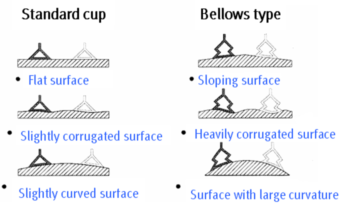
Cup Shape and Surface Match
Shape selection starts with the workpiece surface. Flat suction cups work best on smooth, rigid, and non-porous surfaces such as glass, sheet metal, plastic plate, and machined parts. Their low internal volume evacuates quickly, enabling fast cycle times. They also handle high lateral shear forces well, making them reliable in fast pick-and-place operations where acceleration forces are significant.
Bellows cups introduce one or more accordion-style folds into the body. Those folds allow the cup to compress and angle on contact, accommodating surfaces that are curved, inclined, or inconsistent in height across the part. In practice, bellows cups see heavy use in food packaging, injection-molded plastic handling, and automotive panel work. However, their larger internal volume takes longer to evacuate. This means the vacuum generator needs more flow capacity, and cycle times run longer than flat cups at equivalent vacuum levels.
Oval cups suit elongated workpieces like profiles, door frames, and structural extrusions. Their extended contact footprint in one direction generates more holding force than a round cup of equivalent width. Extra-deep cups occupy a middle ground between flat and bellows designs, handling domed or gently curved surfaces without the cycle-time penalty of a full bellows design.
Material Selection and Environment
Cup material determines how the seal interacts with the workpiece surface, and how the cup holds up to the operating environment. The most common materials each serve distinct conditions.
| Material | Best For | Limitations |
|---|---|---|
| NBR (nitrile rubber) | Oil-resistant applications, general manufacturing | Not suited for high temperatures or ozone exposure |
| Silicone | High and low temperature environments, food contact | Lower abrasion resistance than NBR |
| EPDM | Outdoor use, UV and ozone resistance | Poor performance with oils and fuels |
| Polyurethane | High wear and abrasion applications | Stiffer, less conforming on irregular surfaces |
| Fluoroelastomer (Viton) | Aggressive chemicals, very high temperatures | Higher cost, typically reserved for demanding environments |
Silicone is the default choice for food-contact and cleanroom applications. NBR handles oily metal surfaces well. Polyurethane extends cup life significantly in high-cycle abrasive conditions. Selecting the wrong material accelerates wear, causes seal degradation, and introduces contamination risk where none should exist.
Sizing the Cup Correctly
Larger cups generate more holding force, but they also require more vacuum flow and take longer to reach operating vacuum level. The practical guidance across suppliers is consistent: use the largest cup the application and tooling geometry allow, within the pump’s flow capacity. For multi-cup tooling, total internal volume across all cups determines the flow demand on the vacuum generator. Size the pump to that total, not to any individual cup. Confirm that grip force with the safety factor applied still exceeds the combined weight and acceleration forces the part will experience during the move.
[IMAGE: Comparison diagram showing flat vs. bellows cup cross-sections on a curved workpiece, illustrating conformance and seal contact differences]
4. Integration & Deployment Reality
Mounting and connection geometry determines whether the cup actually performs to spec. Cup port thread size must match the fitting on the manifold or end-of-arm tooling. Mismatched threads leak vacuum at the connection, reducing holding force without any obvious fault. Confirm thread standard (G-thread metric, NPT, or other) before ordering.
Cup spacing on multi-cup EOAT affects both grip stability and cycle time. Cups placed too far apart on a flexible workpiece allow the part to bow between contact points, breaking the seal. Cups placed too close together leave insufficient room for the vacuum fittings and may concentrate force on too small an area of a fragile part. Work from the workpiece geometry outward when designing the tooling layout.
Vacuum sensors are worth treating as standard equipment rather than optional. A sensor monitoring vacuum level at each cup, or at each zone on a multi-cup manifold, catches grip failures before the robot moves the part. Without that feedback, a partial seal failure causes a dropped part at the destination rather than a fault at pickup. Most PLC integrations handle vacuum sensor I/O straightforwardly, but define the fault threshold and response logic before commissioning. Vendor documentation covers sensor wiring; it does not define what vacuum level constitutes an acceptable grip for your specific application.
5. Common Failure Modes & Constraints
Grip and Seal Failures
| Failure | Root Cause | Signal / Symptom |
|---|---|---|
| Grip loss mid-cycle | Surface porosity or contamination breaks seal | Part drops at transfer point; vacuum sensor trips |
| Cup fails to seat | Cup-to-surface geometry mismatch | Vacuum level does not reach threshold; robot holds position |
| Partial seal on curved surface | Flat cup used on curved workpiece | Low vacuum reading; inconsistent grip across cycles |
| Seal lip cracking or tearing | Wrong material for temperature or chemical environment | Visual wear; increasing leak rate over time |
Grip loss and partial sealing are the two most common issues, and both trace back to the initial selection process. A flat cup on a curved surface will never seal consistently, regardless of pump capacity. Similarly, surface contamination breaks any cup’s seal. In food and pharmaceutical environments, surface moisture is a persistent issue. Using a cup material and profile rated for wet or oily surfaces addresses part of the problem, but confirm with a physical trial under actual production conditions before committing to a tooling design.
System and Cycling Failures
| Failure | Root Cause | Signal / Symptom |
|---|---|---|
| Slow cycle time | Cup volume too large for pump flow | Robot waits for vacuum confirmation; cycle extends |
| Cup deforms workpiece | Excessive vacuum level on delicate material | Surface marks or distortion visible after release |
| Cup wears rapidly | High-cycle abrasive surface with wrong material | Seal lip erosion; reduced grip force within weeks |
Cycle time problems often surface after the system is installed, not before. The internal volume of a bellows cup can be three to five times that of a flat cup at the same diameter. If the pump was sized for flat cups and the application changes to bellows, cycle time extends noticeably. Address this at the design stage, not after go-live.
6. When It’s a Good Fit vs. a Bad Fit
Good fit when:
Vacuum gripping excels on non-porous, smooth surfaces where the cup can form a reliable seal. Glass, sheet metal, rigid plastics, and smooth cardboard all fall squarely into this category. The technology also works well where mechanical grippers would mark or damage the workpiece surface, since the cup contacts the surface softly and distributes load across the sealing lip rather than clamping from the edges. High-cycle pick-and-place operations with consistent part geometry and controlled surface conditions represent the core use case, and flat cups in particular handle fast automated movements reliably.
High risk when:
Surface variability creates risk that cup selection alone cannot fully resolve. Parts with oily, wet, or dusty surfaces reduce vacuum reliability even with cups rated for those conditions. Porous materials like unfinished wood, foam, and some cardboard grades allow air to leak through the workpiece itself, collapsing the vacuum regardless of seal quality. These applications require high-flow vacuum systems with leak compensation, and the integrator must validate grip reliability under worst-case surface conditions before signing off. Fragile parts with very low surface deformation tolerance are also high risk. Excessive vacuum level causes surface marks or distortion. The vacuum level must be tuned carefully, and that tuning requires physical testing, not formula-based estimates.
Usually the wrong tool when:
Workpieces with perforations, open mesh, or closely spaced holes defeat vacuum gripping entirely. No cup can seal over a surface that vents freely to atmosphere. Mechanical grippers handle these parts better. Very heavy parts at the edge of a cup’s theoretical capacity are also a poor fit for vacuum-only gripping, particularly in vertical orientations with significant acceleration forces. In those cases, mechanical backstops or hybrid grippers that combine vacuum with a physical catch reduce the risk of a dropped part from what would otherwise be a single-point failure.
7. Key Questions Before Committing
- What is the workpiece surface condition, specifically the flatness, porosity, and any contaminants present during handling, and has a physical grip trial confirmed that the selected cup material and profile achieve a reliable seal under those actual conditions?
- What is the required cycle time from cup contact to confirmed vacuum, and does the pump’s flow rate and the cup’s internal volume support that timing across all cups in the tooling simultaneously?
- Does the workpiece surface tolerance allow the vacuum level needed for the required holding force, and has the team confirmed that full operating vacuum will not mark, distort, or stress the part material?
- What is the operating environment temperature range, and does the selected cup material maintain its sealing properties and physical integrity across that full range?
- Is there a vacuum sensor in the system to confirm grip quality before each robot move, and does the PLC logic define a specific fault response if vacuum falls below the grip threshold?
8. How Axis Recommends Using This Information
Axis starts every vacuum gripping evaluation with the workpiece, not the catalog. Surface condition, geometry, and environmental factors determine which cup families are even in consideration before discussing brand or pricing. Skipping that step and selecting a cup based on catalog descriptions alone produces systems that work in trials and fail in production when real surface variation appears.
For new applications, Axis recommends physical grip trials with representative samples from actual production, not prototype parts. Surface finish, contamination, and material consistency often differ between development and production parts. A cup that seals cleanly on a lab sample may struggle on a production part with a different surface treatment or a slightly different radius. Testing on real production samples avoids that gap.
Beyond initial selection, Axis treats vacuum sensors and defined maintenance intervals as standard elements of any vacuum gripping system. Cup wear is gradual and predictable, but it goes undetected without a monitoring baseline. Establishing the expected vacuum level at a known-good cup condition, then tracking that value over time, gives the maintenance team early warning before grip failures start occurring on the line.